
How to Calculate the Resolution of a Load Cell
Per Section 4.14 of JCGM 200:2012, Resolution is the “smallest change in a quantity being measured that causes a perceptible change in the corresponding indication.” Over the years, this simple definition has become a topic of confusion in the metrology community. We are hoping to simplify how to calculate the resolution of the Unit Under Test (UUT) so this can be a simple guidance document. However, we are first going to briefly discuss why calculating the resolution of the Unit Under Test properly is essential.
Morehouse reports the resolution of the Unit Under Test on our calibration certificates as well as uses the resolution of in the divisor for calculating TUR and reporting Expanded Uncertainty. TUR is defined in ANSI/NCSLI Z540.3-2006 and ILAC G8, as “The ratio of the span of the tolerance of a measurement quantity subject to calibration, to twice the 95 % expanded uncertainty of the measurement process used for calibration”. This calculation of TUR is crucial as it is the basis for making statements of conformity required by ISO/IEC 17025:2017section 7.8.6.1 & 2.
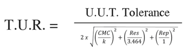
Figure 1 The typical minimum contributors to calculate TUR at the time of calibration
We typically deal with the resolution of the UUT in the denominator, as shown in Figure 1 above. ANSI/NCSL Z540.3 Handbook states, “For the denominator, the 95 % expanded uncertainty of the measurement process used for calibration per the calibration procedure is to be used to calculate TUR. The value of this uncertainty, the estimate should reflect the results that are reasonably expected from the use of the approved procedure to calibrate the particular type of M&TE.
Therefore, the estimate includes all components of the error that have an influence on the measurement results of the calibration which would also include the influences of the item being calibrated, with the exception of the bias of the M&TE. The calibration process error, therefore, includes temporary and non-correctable influences incurred during the calibration such as repeatability, resolution, error in the measurement source, operator error, error in correction factors, environmental influences, etc.”
ILAC P-14 addresses resolution as part of the Expanded Uncertainty in section 6.4 which states, “Contributions to the uncertainty stated on the calibration certificate shall include relevant short-term contributions during calibration and contributions that can reasonably be attributed to the customer’s device. Where applicable the uncertainty shall cover the same contributions to the uncertainty that were included in the evaluation of the CMC uncertainty component, except that the uncertainty component evaluated for the best existing device shall be replaced with those of the customer’s device.”
Now that we’ve hopefully made a case for why we need to know the resolution of the UUT, we can discuss various methods for calculating the resolution. Here at Morehouse, we often get asked, how do you calculate resolution? The answer is we take the force applied value and divide it by the output of the UUT at the corresponding point, and multiply that number by the readability. Let’s look at one example. In Example 1, we have a 10,000 lbf load cell with an output of 4.11235 mV/V, and the force-measuring device is read at the fifth decimal (0.00001), and the display counts by 1
Example 1: Device Reads in mV/V & Counts by 1
| Force Applied | Measured Output of UUT | Readability of UUT | Count by |
| 10,000 | 4.11235 | 0.00001 | 1 |
| Resolution = | ((10,000 / 4.11235) *0.00001)*1 = | 0.02432 |
In our next example, we have a 10,000 lbf load cell with an output of 4.11235 mV/V, and the force-measuring device is read at the fifth decimal 0.00001, and the display counts by 5
Example 2: Device Reads in mV/V & Counts by 5
| Force Applied | Measured Output of UUT | Readability of UUT | Count by |
| 10,000 | 4.11235 | 0.00001 | 5 |
| Resolution = | ((10,000 / 4.11235) *0.00001)*5 = | 0.12158 |
In example 3, we have multiple force points or numerous readings at the same force point; we would take the average of the force points and apply the same formula.
| Example 3: | 2 Measured Values Device | Reads in mV/V and Counts by 1 |
| Force Applied | Measured Output of UUT | Measured Output of UUT |
| Run 1 | Run2 | |
| 10,000 | 4.11235 | 4.11325 |
| Average Output | Readability of UUT | Count by |
| 4.1128 | 0.00001 | 1 |
| Resolution = | ((10,000 / 4.11228) *0.00001)*1 = | 0.02431 |
We use this formula for all scenarios, even when the indicator counts in force units, as shown in example 4.
| Example 4: | Device Reads in lbf | ||
| Force Applied | Measured Output of UUT | Readability of UUT | Count by |
| 10,000 | 10250.5 | 0.1 | 5 |
| Resolution= | ((10,000 / 10,250.5) *0.1)*5= | 0.488 |
If we have multiple force points, we should then take the average resolution is shown in example 5.
| Example 5: | Multiple Points mV/V | |||
| Force Applied | Measured Output of UUT | Readability of UUT | Count by | Resolution |
| 2,000 | 0.82199 | 0.00001 | 1 | 0.02433 |
| 4,000 | 1.64316 | 0.00001 | 1 | 0.02434 |
| 6,000 | 2.46741 | 0.00001 | 1 | 0.02432 |
| 8,000 | 3.28632 | 0.00001 | 1 | 0.02434 |
| 10,000 | 4.11235 | 0.00001 | 1 | 0.02432 |
| Average Resolution | 0.02433 | |||
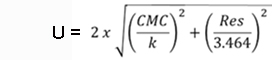
Figure 2 minimum contributors for Expanded Uncertainty calculation at the time of calibration for 95 % confidence
Note: Resolution may either be divided by a rectangular distribution or by the square root of 12 as shown above. Dilip Shah has written a lot more on the topic which can be found at http://asq.org/quality-progress/2016/09/measure-for-measure/resolution-resolve.html. Dilip and Henry teach force classes with uncertainty at Morehouse Instrument Company. Anyone wishing to learn more should check out our Training Courses.
How to Calculate the Resolution of a Load Cell - Conclusion:
In the five examples provided above, not many changes in the formula, we either take a single point value of the instrument's measured value at capacity, use the formula for the average deflection values, or take the average over all of the points in the measuring range. We multiply this value by the readability and then multiply by how much the instrument counts by. The resolution is then used in reporting the Expanded Uncertainty, which is shown in Figure 2, which complies with the requirements of ILAC P-14 Policy for Uncertainty in Calibration.
If you have additional questions, please contact us at info@mhforce.com. We are here to help you improve your force and torque measurements.
If you enjoyed this article, check out our LinkedIn and YouTube channel for more helpful posts and videos.
Everything we do, we believe in changing how people think about force and torque calibration. Morehouse believes in thinking differently about force and torque calibration and equipment. We challenge the "just calibrate it" mentality by educating our customers on what matters, and what causes significant errors, and focus on reducing them.
Morehouse makes our products simple to use and user-friendly. And we happen to make great force equipment and provide unparalleled calibration services.
Wanna do business with a company that focuses on what matters most? Email us at info@mhforce.com.
# How to Calculate the Resolution of a Load Cell

